Definition of Important Terms
The key performance parameters of centrifugal pumps are capacity, head, BHP (Brake horse power), BEP (Best efficiency point) and specific speed. The pump curves provide the operating window within which these parameters can be varied for satisfactory pump operation. The following parameters or terms are discussed in detail in this section.
· Capacity
· Head
Significance of using Head instead of Pressure
Pressure to Head Conversion formula
Static Suction Head, hS
Static Discharge Head, hd
Friction Head, hf
Vapor pressure Head, hvp
Pressure Head, hp
Velocity Head, hv
Total Suction Head HS
Total Discharge Head Hd
Total Differential Head HT
· NPSH
Net Positive Suction Head Required NPSHr
Net Positive Suction Head Available NPSHa
· Power (Brake Horse Power, B.H.P) and Efficiency (Best Efficiency Point, B.E.P)
· Specific Speed (Ns)
· Affinity Laws
Capacity
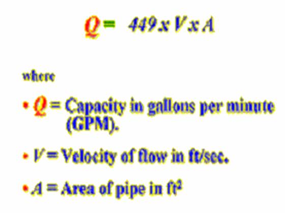
Capacity means the flow rate with which liquid is moved or pushed by the pump to the desired point in the process. It is commonly measured in either gallons per minute (gpm) or cubic meters per hour (m3/hr). The capacity usually changes with the changes in operation of the process. For example, a boiler feed pump is an application that needs a constant pressure with varying capacities to meet a changing steam demand.
The capacity depends on a number of factors like:
· Process liquid characteristics i.e. density, viscosity
· Size of the pump and its inlet and outlet sections
· Impeller size
· Impeller rotational speed RPM
· Size and shape of cavities between the vanes
· Pump suction and discharge temperature and pressure conditions
For a pump with a particular impeller running at a certain speed in a liquid, the only items on the list above that can change the amount flowing through the pump are the pressures at the pump inlet and outlet. The effect on the flow through a pump by changing the outlet pressures is graphed on a pump curve.
As liquids are essentially incompressible, the capacity is directly related with the velocity of flow in the suction pipe. This relationship is as follows:
Head
Significance of using the “head” term instead of the “pressure” term
The pressure at any point in a liquid can be thought of as being caused by a vertical column of the liquid due to its weight. The height of this column is called the static head and is expressed in terms of feet of liquid.
The same head term is used to measure the kinetic energy created by the pump. In other words, head is a measurement of the height of a liquid column that the pump could create from the kinetic energy imparted to the liquid. Imagine a pipe shooting a jet of water straight up into the air, the height the water goes up would be the head.
The head is not equivalent to pressure. Head is a term that has units of a length or feet and pressure has units of force per unit area or pound per square inch. The main reason for using head instead of pressure to measure a centrifugal pump's energy is that the pressure from a pump will change if the specific gravity (weight) of the liquid changes, but the head will not change. Since any given centrifugal pump can move a lot of different fluids, with different specific gravities, it is simpler to discuss the pump's head and forget about the pressure.
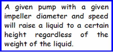
So a centrifugal pump’s performance on any Newtonian fluid, whether it's heavy (sulfuric acid) or light (gasoline) is described by using the term ‘head’. The pump performance curves are mostly described in terms of head.
Pressure to Head Conversion formula
The static head corresponding to any specific pressure is dependent upon the weight of the liquid according to the following formula:
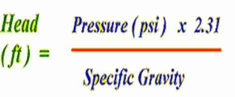
Newtonian liquids have specific gravities typically ranging from 0.5 (light, like light hydrocarbons) to 1.8 (heavy, like concentrated sulfuric acid). Water is a benchmark, having a specific gravity of 1.0.
This formula helps in converting pump gauge pressures to head for reading the pump curves.
The various head terms are discussed below.
Note: The Subscripts ‘s’ refers to suction conditions and ‘d’ refers to discharge conditions.
Static Suction Head, hS
Static Discharge Head, hd
Friction Head, hf
Vapor pressure Head, hvp
Pressure Head, hp
Velocity Head, hv
Total Suction Head HS
Total Discharge Head Hd
Total Differential Head HT
Net Positive Suction Head Required NPSHr
Net Positive Suction Head Available NPSHa
· Static Suction Head (hS) : Head resulting from elevation of the liquid relative to the pump center line. If the liquid level is above pump centerline, hS is positive. If the liquid level is below pump centerline, hS is negative. Negative hS condition is commonly denoted as a “suction lift” condition
· Static Discharge Head (hd): It is the vertical distance in feet between the pump centerline and the point of free discharge or the surface of the liquid in the discharge tank.
· Friction Head (hf): The head required to overcome the resistance to flow in the pipe and fittings. It is dependent upon the size, condition and type of pipe, number and type of pipefittings, flow rate, and nature of the liquid.
· Vapor Pressure Head (hvp): Vapor pressure is the pressure at which a liquid and its vapor co-exist in equilibrium at a given temperature. The vapor pressure of liquid can be obtained from vapor pressure tables. When the vapor pressure is converted to head, it is referred to as vapor pressure head, hvp. The value of hvp of a liquid increases with the rising temperature and in effect, opposes the pressure on the liquid surface, the positive force that tends to cause liquid flow into the pump suction i.e. it reduces the suction pressure head.
· Pressure Head (hp): Pressure Head must be considered when a pumping system either begins or terminates in a tank which is under some pressure other than atmospheric. The pressure in such a tank must first be converted to feet of liquid. Denoted as hp, pressure head refers to absolute pressure on the surface of the liquid reservoir supplying the pump suction, converted to feet of head. If the system is open, hp equals atmospheric pressure head.
· Velocity Head (hv): Refers to the energy of a liquid as a result of its motion at some velocity ‘v’. It is the equivalent head in feet through which the water would have to fall to acquire the same velocity, or in other words, the head necessary to accelerate the water. The velocity head is usually insignificant and can be ignored in most high head systems. However, it can be a large factor and must be considered in low head systems.
· Total Suction Head (HS): The suction reservoir pressure head (hpS) plus the static suction head (hS) plus the velocity head at the pump suction flange (hVS) minus the friction head in the suction line (hfS).
HS = hpS + hS + hvS – hfS
The total suction head is the reading of the gauge on the suction flange, converted to feet of liquid.
· Total Discharge Head (Hd): The discharge reservoir pressure head (hpd) plus static discharge head (hd) plus the velocity head at the pump discharge flange (hvd) plus the total friction head in the discharge line (hfd).
Hd = hpd + hd + hvd + hfd
The total discharge head is the reading of a gauge at the discharge flange, converted to feet of liquid.
· Total Differential Head (HT): It is the total discharge head minus the total suction head or
HT
= Hd + HS (with a suction lift)
HT
= Hd - HS (with a suction head)
NPSH
When discussing centrifugal pumps, the two most important head terms are NPSHr and NPSHa.
Net Positive Suction Head Required, NPSHr
NPSH is one of the most widely used and least understood terms associated with pumps. Understanding the significance of NPSH is very much essential during installation as well as operation of the pumps.
Pumps
can pump only liquids, not vapors
The satisfactory operation of a pump requires that vaporization of the liquid being pumped does not occur at any condition of operation. This is so desired because when a liquid vaporizes its volume increases very much. For example, 1 ft3 of water at room temperature becomes 1700 ft3 of vapor at the same temperature. This makes it clear that if we are to pump a fluid effectively, it must be kept always in the liquid form.
Rise in temperature and fall in pressure induces vaporization
The vaporization begins when the vapor pressure of the liquid at the operating temperature equals the external system pressure, which, in an open system is always equal to atmospheric pressure. Any decrease in external pressure or rise in operating temperature can induce vaporization and the pump stops pumping. Thus, the pump always needs to have a sufficient amount of suction head present to prevent this vaporization at the lowest pressure point in the pump.
NPSH as a measure to prevent liquid vaporization
The manufacturer usually tests the pump with water at different capacities, created by throttling the suction side. When the first signs of vaporization induced cavitation occur, the suction pressure is noted (the term cavitation is discussed in detail later). This pressure is converted into the head. This head number is published on the pump curve and is referred as the "net positive suction head required (NPSHr) or sometimes in short as the NPSH. Thus the Net Positive Suction Head (NPSH) is the total head at the suction flange of the pump less the vapor pressure converted to fluid column height of the liquid.
NPSH
is a function of pump design
NPSH required is a function of the pump design and is determined based on actual pump test by the vendor. As the liquid passes from the pump suction to the eye of the impeller, the velocity increases and the pressure decreases. There are also pressure losses due to shock and turbulence as the liquid strikes the impeller. The centrifugal force of the impeller vanes further increases the velocity and decreases the pressure of the liquid. The NPSH required is the positive head in feet absolute required at the pump suction to overcome these pressure drops in the pump and maintain the majority of the liquid above its vapor pressure.
The NPSH is always positive since it is expressed in terms of absolute fluid column height. The term "Net" refers to the actual pressure head at the pump suction flange and not the static suction head.
NPSHr increases as capacity increases
The NPSH required varies with speed and capacity within any particular pump. The NPSH required increase as the capacity is increasing because the velocity of the liquid is increasing, and as anytime the velocity of a liquid goes up, the pressure or head comes down.
Pump manufacturer's curves normally provide this information. The NPSH is independent of the fluid density as are all head terms.
Note: It is to be noted that the net positive suction head required (NPSHr) number shown on the pump curves is for fresh water at 20°C and not for the fluid or combinations of fluids being pumped.
Net Positive Suction Head available, NPSHa
NPSHa
is a function of system design
Net
Positive Suction Head Available is a function of the system in which
the pump operates. It is the excess pressure of the liquid in
feet absolute over its vapor pressure as it arrives at the pump
suction, to be sure that the pump selected does not cavitate.
It is calculated based on system or process conditions.
NPSHa
calculation
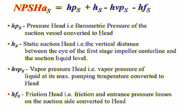
The formula for calculating the NPSHa is stated below:
Note:
1. It is important to correct for the specific gravity of the liquid and to convert all terms to units of "feet absolute" in using the formula.
2. Any discussion of NPSH or cavitation is only concerned about the suction side of the pump. There is almost always plenty of pressure on the discharge side of the pump to prevent the fluid from vaporizing.
NPSHa in a nutshell
In a nutshell, NPSH available is defined as:
NPSHa = Pressure head + Static head - Vapor pressure head of your product – Friction head loss in the piping, valves and fittings.
“All terms in feet absolute”
In an existing system, the NPSHa can also be approximated by a gauge on the pump suction using the formula:
NPSHa = hpS - hvpS ± hgS + hvS
§ hpS = Barometric pressure in feet absolute.
§ hvpS = Vapor pressure of the liquid at maximum pumping temperature, in feet absolute.
§ hgS = Gauge reading at the pump suction expressed in feet (plus if above atmospheric, minus if below atmospheric) corrected to the pump centerline.
§ hvS = Velocity head in the suction pipe at the gauge connection, expressed in feet.
Significance of NPSHr and NPSHa
The NPSH available must always be greater than the NPSH required for the pump to operate properly. It is normal practice to have at least 2 to 3 feet of extra NPSH available at the suction flange to avoid any problems at the duty point.
Power and Efficiency
Brake Horse Power (BHP)
The work performed by a pump is a function of the total head and the weight of the liquid pumped in a given time period.
Pump input or brake horsepower (BHP) is the actual horsepower delivered to the pump shaft.
Pump output or hydraulic or water horsepower (WHP) is the liquid horsepower delivered by the pump. These two terms are defined by the following formulas.
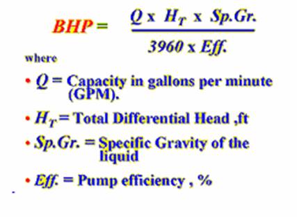
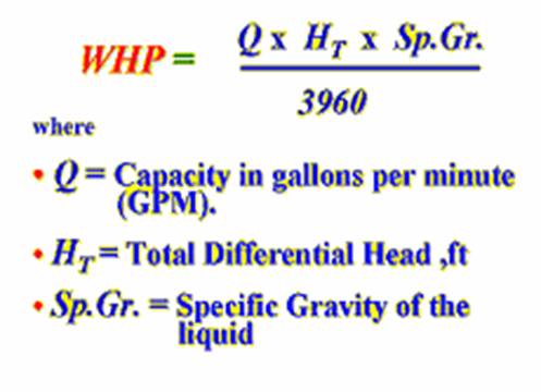
The constant 3960 is obtained by dividing the number or foot-pounds for one horsepower (33,000) by the weight of one gallon of water (8.33 pounds).
BHP can also be read from the pump curves at any flow rate. Pump curves are based on a specific gravity of 1.0. Other liquids’ specific gravity must be considered.
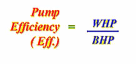
The brake horsepower or input to a pump is greater than the hydraulic horsepower or output due to the mechanical and hydraulic losses incurred in the pump.
Therefore the pump efficiency is the ratio of these two values.
Best Efficiency Point (BEP)
The H, NPSHr, efficiency, and BHP all vary with flow rate, Q. Best Efficiency Point (BEP) is the capacity at maximum impeller diameter at which the efficiency is highest. All points to the right or left of BEP have a lower efficiency.
Significance of BEP
BEP as a measure of optimum energy conversion
When sizing and selecting centrifugal pumps for a given application the pump efficiency at design should be taken into consideration. The efficiency of centrifugal pumps is stated as a percentage and represents a unit of measure describing the change of centrifugal force (expressed as the velocity of the fluid) into pressure energy. The B.E.P. (best efficiency point) is the area on the curve where the change of velocity energy into pressure energy at a given gallon per minute is optimum; in essence, the point where the pump is most efficient.
BEP as a measure of mechanically stable operation
The impeller is subject to non-symmetrical forces when operating to the right or left of the BEP. These forces manifest themselves in many mechanically unstable conditions like vibration, excessive hydraulic thrust, temperature rise, and erosion and separation cavitation. Thus the operation of a centrifugal pump should not be outside the furthest left or right efficiency curves published by the manufacturer. Performance in these areas induces premature bearing and mechanical seal failures due to shaft deflection, and an increase in temperature of the process fluid in the pump casing causing seizure of close tolerance parts and cavitation.
BEP as an important parameter in calculations
BEP is an important parameter in that many parametric calculations such as specific speed, suction specific speed, hydrodynamic size, viscosity correction, head rise to shut-off, etc. are based on capacity at BEP. Many users prefer that pumps operate within 80% to 110% of BEP for optimum performance.
Specific Speed
Specific speed as a measure of the geometric similarity of pumps
Specific speed (Ns) is a non-dimensional design index that identifies the geometric similarity of pumps. It is used to classify pump impellers as to their type and proportions. Pumps of the same Ns but of different size are considered to be geometrically similar, one pump being a size-factor of the other.
Specific speed Calculation
The following formula is used to determine specific speed:
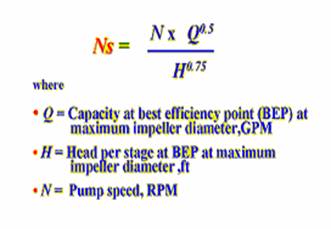
As per the above formula, it is defined as the speed in revolutions per minute at which a geometrically similar impeller would operate if it were of such a size as to deliver one gallon per minute flow against one-foot head.
The understanding of this definition is of design engineering significance only, however, and specific speed should be thought of only as an index used to predict certain pump characteristics.
Specific speed as a measure of the shape or class of the impellers
The specific speed determines the general shape or class of the impellers. As the specific speed increases, the ratio of the impeller outlet diameter, D2, to the inlet or eye diameter, D1, decreases. This ratio becomes 1.0 for a true axial flow impeller. Radial flow impellers develop head principally through centrifugal force. Radial impellers are generally low flow high head designs. Pumps of higher specific speeds develop head partly by centrifugal force and partly by axial force. A higher specific speed indicates a pump design with head generation more by axial forces and less by centrifugal forces. An axial flow or propeller pump with a specific speed of 10,000 or greater generates its head exclusively through axial forces. Axial flow impellers are high flow low head designs.
· Specific speed identifies the approximate acceptable ratio of the impeller eye diameter (D1) to the impeller maximum diameter (D2) in designing a good impeller.
Ns:
500 to 5000; D1/D2 > 1.5
- radial flow pump
Ns: 5000 to 10000; D1/D2 <
1.5 - mixed flow pump
Ns: 10000 to 15000; D1/D2 = 1
- axial flow pump
Specific speed is also used in designing a new pump by size-factoring a smaller pump of the same specific speed. The performance and construction of the smaller pump are used to predict the performance and model the construction of the new pump.
Suction specific speed (Nss)
Suction specific speed (Nss) is a dimensionless number or index that defines the suction characteristics of a pump. It is calculated from the same formula as Ns by substituting H by NPSHr.
In multi-stage pump the NPSHr is based on the first stage impeller NPSHR.
Specific speed as a measure of the safe operating range
Nss is commonly used as a basis for estimating the safe operating range of capacity for a pump. The higher the Nss is, the narrower is its safe operating range from its BEP. The numbers range between 3,000 and 20,000. Most users prefer that their pumps have Nss in the range of 8000 to 11000 for optimum and trouble-free operation.
The Affinity Laws
The Affinity Laws are mathematical expressions that define changes in pump capacity, head, and BHP when a change is made to pump speed, impeller diameter, or both. According to Affinity Laws:
· Capacity, Q changes in direct proportion to impeller diameter D ratio, or to speed N ratio:
Q2
= Q1 x [D2/D1]
Q2 = Q1 x [N2/N1]
· Head, H changes in direct proportion to the square of impeller diameter D ratio, or the square of speed N ratio:
H2
= H1 x [D2/D1]2
H2 = H1 x [N2/N1]2
· BHP changes in direct proportion to the cube of impeller diameter ratio, or the cube of speed ratio:
BHP2
= BHP1 x [D2/D1]3
BHP2 = BHP1 x [N2/N1]3
Where the subscript: 1 refers to initial condition, 2 refer to new condition
If changes are made to both impeller diameter and pump speed the equations can be combined to:
Q2 = Q1 x [(D2xN2)/(D1xN1)]
H2 = H1 x [(D2xN2)/(D1xN1)]2
BHP2 = BHP1 x [(D2xN2)/(D1xN1)]3
This equation is used to hand-calculate the impeller trim diameter from a given pump performance curve at a bigger diameter.
The Affinity Laws are valid only under conditions of constant efficiency.