General Components of Centrifugal Pumps
A centrifugal pump has two main components:
I. A rotating component comprised of an impeller and a shaft
II. A stationary component comprised of a casing, casing cover, and bearings.
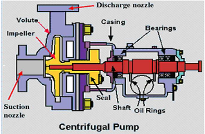
The general components, both stationary and rotary, are depicted in Figure B.01. The main components are discussed in brief below. Figure B.02 shows these parts on a photograph of a pump in the field.
Figure B.01: General components of Centrifugal Pump
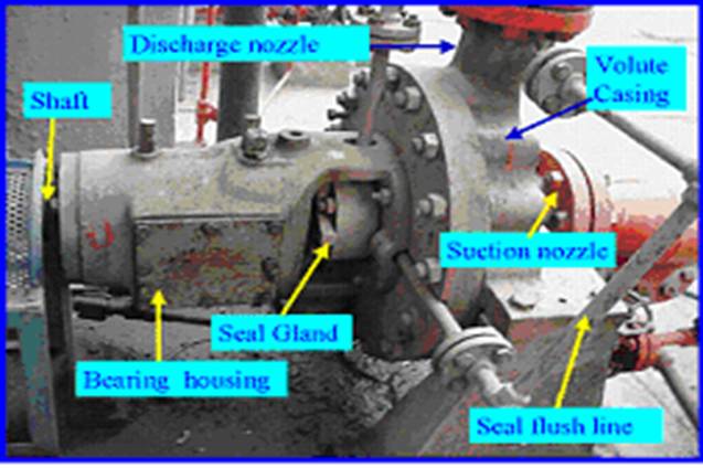
Figure B.02: General components of a Centrifugal Pump
Casing
Casings are generally of two types: volute and circular. The impellers are fitted inside the casings.
1.
Volute casings build a higher head; circular casings are used for low
head and high capacity.
o A volute is a curved funnel increasing in area to the discharge port as shown in Figure B.03. As the area of the cross-section increases, the volute reduces the speed of the liquid and increases the pressure of the liquid.
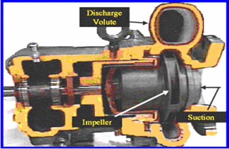
Figure
B.03: Cut-away of a pump showing volute casing
o One of the main purposes of a volute casing is to help balance the hydraulic pressure on the shaft of the pump. However, this occurs best at the manufacturer's recommended capacity. Running volute-style pumps at a lower capacity than the manufacturer recommends can put lateral stress on the shaft of the pump, increasing wear-and-tear on the seals and bearings, and on the shaft itself. Double-volute casings are used when the radial thrusts become significant at reduced capacities.
2. Circular casing have stationary diffusion vanes surrounding the impeller periphery that convert velocity energy to pressure energy. Conventionally, the diffusers are applied to multi-stage pumps.
Figure
B.04: Solid Casing
o The casings can be designed either as solid casings or split casings. Solid casing implies a design in which the entire casing including the discharge nozzle is all contained in one casting or fabricated piece. A split casing implies two or more parts are fastened together. When the casing parts are divided by horizontal plane, the casing is described as horizontally split or axially split casing. When the split is in a vertical plane perpendicular to the rotation axis, the casing is described as vertically split or radially split casing. Casing Wear rings act as the seal between the casing and the impeller.
Suction and Discharge Nozzle
The suction and discharge nozzles are part of the casings itself. They commonly have the following configurations.
1. End suction/Top discharge (Figure B.05) - The suction nozzle is located at the end of, and concentric to, the shaft while the discharge nozzle is located at the top of the case perpendicular to the shaft. This pump is always of an overhung type and typically has lower NPSHr because the liquid feeds directly into the impeller eye.
2. Top suction Top discharge nozzle (Figure B.05) -The suction and discharge nozzles are located at the top of the case perpendicular to the shaft. This pump can either be an overhung type or between-bearing type but is always a radially split case pump.
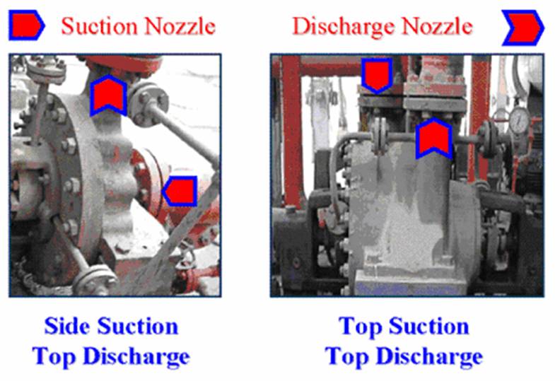
Figure B.05: Suction and Discharge Nozzle Locations
3. Side suction / Side discharge nozzles - The suction and discharge nozzles are located at the sides of the case perpendicular to the shaft. This pump can have either an axially or radially split case type.
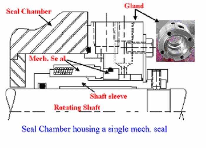
Seal Chamber and Stuffing Box Seal chamber and Stuffing box both refer to a chamber, either integral with or separate from the pump case housing that forms the region between the shaft and casing where sealing media are installed. When the sealing is achieved by means of a mechanical seal, the chamber is commonly referred to as a Seal Chamber. When the sealing is achieved by means of packing, the chamber is referred to as a Stuffing Box. Both the seal chamber and the stuffing box have the primary function of protecting the pump against leakage at the point where the shaft passes out through the pump pressure casing. When the pressure at the bottom of the chamber is below atmospheric, it prevents air leakage into the pump. When the pressure is above atmospheric, the chambers prevent liquid leakage out of the pump. The seal chambers and stuffing boxes are also provided with cooling or heating arrangement for proper temperature control. Figure B.06 below depicts an externally mounted seal chamber and its parts.
Figure
B.06: Parts of a simple Seal Chamber
o Gland: The gland is a very important part of the seal chamber or the stuffing box. It gives the packings or the mechanical seal the desired fit on the shaft sleeve. It can be easily adjusted in axial direction. The gland comprises of the seal flush, quench, cooling, drain, and vent connection ports as per the standard codes like API 682.
o Throat Bushing: The bottom or inside end of the chamber is provided with a stationary device called throat bushing that forms a restrictive close clearance around the sleeve (or shaft) between the seal and the impeller.
o Throttle bushing refers to a device that forms a restrictive close clearance around the sleeve (or shaft) at the outboard end of a mechanical seal gland.
o Internal circulating device refers to device located in the seal chamber to circulate seal chamber fluid through a cooler or barrier/buffer fluid reservoir. Usually it is referred to as a pumping ring.
o Mechanical Seal: The features of a mechanical seal will be discussed in Part-II of the article.
Bearing housing
The bearing housing encloses the bearings mounted on the shaft. The bearings keep the shaft or rotor in correct alignment with the stationary parts under the action of radial and transverse loads. The bearing house also includes an oil reservoir for lubrication, constant level oiler, jacket for cooling by circulating cooling water.
Rotating Components
1. Impeller
The impeller is the main rotating part that provides the centrifugal acceleration to the fluid. They are often classified in many ways.
o Based on major direction of flow in reference to the axis of rotation
§ Radial flow
§ Axial flow
§ Mixed flow
o Based on suction type
§ Single-suction: Liquid inlet on one side.
§ Double-suction: Liquid inlet to the impeller symmetrically from both sides.
o Based on mechanical construction (Figure B.07)
§ Closed: Shrouds or sidewall enclosing the vanes.
§ Open: No shrouds or wall to enclose the vanes.
§ Semi-open or vortex type.
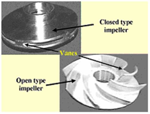
Figure
B.07: Impeller types
Closed impellers require wear rings and these wear rings present another maintenance problem. Open and semi-open impellers are less likely to clog, but need manual adjustment to the volute or back-plate to get the proper impeller setting and prevent internal re-circulation. Vortex pump impellers are great for solids and "stringy" materials but they are up to 50% less efficient than conventional designs. The number of impellers determines the number of stages of the pump. A single stage pump has one impeller only and is best for low head service. A two-stage pump has two impellers in series for medium head service. A multi-stage pump has three or more impellers in series for high head service.
o Wear rings: Wear ring provides an easily and economically renewable leakage joint between the impeller and the casing. clearance becomes too large the pump efficiency will be lowered causing heat and vibration problems. Most manufacturers require that you disassemble the pump to check the wear ring clearance and replace the rings when this clearance doubles.
2. Shaft
The basic purpose of a centrifugal pump shaft is to transmit the torques encountered when starting and during operation while supporting the impeller and other rotating parts. It must do this job with a deflection less than the minimum clearance between the rotating and stationary parts.
o Shaft Sleeve (Figure B.08): Pump shafts are usually protected from erosion, corrosion, and wear at the seal chambers, leakage joints, internal bearings, and in the waterways by renewable sleeves. Unless otherwise specified, a shaft sleeve of wear, corrosion, and erosion-resistant material shall be provided to protect the shaft. The sleeve shall be sealed at one end. The shaft sleeve assembly shall extend beyond the outer face of the seal gland plate. (Leakage between the shaft and the sleeve should not be confused with leakage through the mechanical seal).
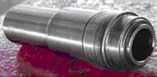
Figure
B.08: A view of a shaft sleeve
o Coupling: Couplings can compensate for axial growth of the shaft and transmit torque to the impeller. Shaft couplings can be broadly classified into two groups: rigid and flexible. Rigid couplings are used in applications where there is absolutely no possibility or room for any misalignment. Flexible shaft couplings are more prone to selection, installation and maintenance errors. Flexible shaft couplings can be divided into two basic groups: elastomeric and non-elastomeric
§ Elastomeric couplings use either rubber or polymer elements to achieve flexibility. These elements can either be in shear or in compression. Tire and rubber sleeve designs are elastomer in shear couplings; jaw and pin and bushing designs are elastomer in compression couplings.
§ Non-elastomeric couplings use metallic elements to obtain flexibility. These can be one of two types: lubricated or non-lubricated. Lubricated designs accommodate misalignment by the sliding action of their components, hence the need for lubrication. The non-lubricated designs accommodate misalignment through flexing. Gear, grid and chain couplings are examples of non-elastomeric, lubricated couplings. Disc and diaphragm couplings are non-elastomeric and non-lubricated.
Auxiliary Components
Auxiliary components generally include the following piping systems for the following services:
o Seal flushing , cooling , quenching systems
o Seal drains and vents
o Bearing lubrication , cooling systems
o Seal chamber or stuffing box cooling, heating systems
o Pump pedestal cooling systems
Auxiliary piping systems include tubing, piping, isolating valves, control valves, relief valves, temperature gauges and thermocouples, pressure gauges, sight flow indicators, orifices, seal flush coolers, dual seal barrier/buffer fluid reservoirs, and all related vents and drains.